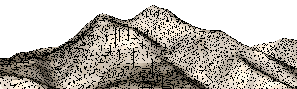
2.5D Delaunay triangulations (TIN – Triangulated Irregular Networks) are like a 2D Delaunay triangulation, but with elevated points. This article first describes the simple triangulation of point clouds from LiDAR scans and surface metrology data. It then demonstrates their optional simplification using adaptive and grid-based clustering methods. Finally, it shows how to re-export the triangle-mesh to your own data structures.
For clarity, this example consists of the Sub-Examples 0-4, each comprising only a few lines of code. You can find the C++ source code as part of the Fade download in the file “examples_25D/a_terrain25d.cpp“.
Generating Points
The function getInputPoints() in the example source code takes a filename and returns a vector of points.
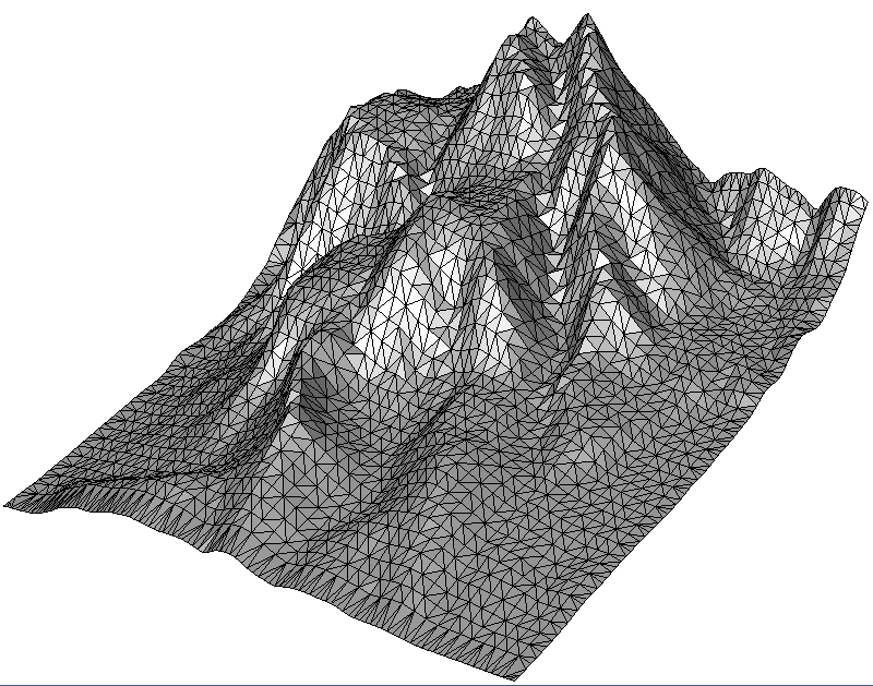
- The special filename “MOUNTAIN” yields a small predefined demo point-cloud with 9240 points (105×88)
- An empty filename yields a random 2.5D surface point cloud. To learn more, see
generateRandomSurfacePoints()in the module Test Data Generators. - Any other filename names a “x y z”-ASCII file. You can substitute the name of your own file here. See
readXYZ()in the module File I/O where various read/write functions for ASCII and binary files are documented.
void getInputPoints(const std::string& filename,
					std::vector<Point2>& vPointsOut)
{
	if(filename=="MOUNTAIN")
	{
		getMountain(vPointsOut);
	}
	else if(!filename.empty())
	{
		// Read terrain points from an ASCII file
		readXYZ(filename.c_str(),vPointsOut);
	}
	else
	{
		// No file given, create a random surface for the demo
		generateRandomSurfacePoints(
			100, // numPointsX
			100, // numPointsY
			200, // numCenters (waviness)
			0,0,0,100,100,50, // Bounds xmin,ymin,zmin,xmax,ymax,zmax
			vPointsOut, // Output vector
			1  // Seed (0 is random, >0 is static)
			);
	}
	std::cout<<"Original number of points: "<<vPointsOut.size()<<endl;
}
2.5D Delaunay Triangulation
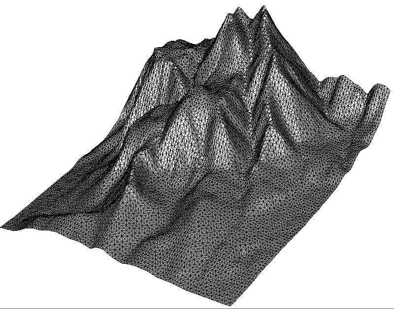
The code snippet below represents Sub-Example 0. Its Step1 uses the getInputPoints()function described above to fetch points. Then Step2 makes performance settings, creates a CloudPrepare object, adds the points to it and finally inserts the CloudPrepare object into the 2.5D Delaunay triangulation. Finally, Step3 saves the result as a .vtk file that can be viewed with Paraview. Alternative file formats are .obj file (supported by practically any 3D viewer) and .list for Geomview (Linux).

// 0: Triangulate all points
void terrain_full()
{
	// * Step 1 *   Get input points
	std::vector<Point2> vInputPoints;
	getInputPoints("MOUNTAIN",vInputPoints);

	// * Step 2 *   Triangulate
	Fade_2D dt;
	dt.setFastMode(true); // Fast mode greatly accelerates raster points
    dt.setNumCPU(0); // 0 means: autodetect
	// dt.insert(vInputPoints); // Still possible but CloudPrepare is recommended
	CloudPrepare cloudPrep;
	cloudPrep.add(vInputPoints);
	dt.insert(&cloudPrep,true); // More memory efficient

	// * Step 3 *   Show
	write(0,"terrain_full",dt);
}
“You could also insert the vector with the points directly in
Fade_2D. However, doing it via theCloudPrepareobject has a practical advantage: Since adding the points toCloudPrepareand inserting theCloudPrepareobject into the Delaunay triangulation are two individual steps, you have the opportunity to delete the points from the data structures of your own software in an intermediate step i.e., before any additional memory for triangles is reserved by Fade. Otherwise, the points would reside twice in memory for a short time. This avoids memory consumption peaks.”
“The code above makes two performance settings:
1.
Fade_2D::setFastMode(true)enables a triangulation mode that accelerates triangulation of raster data (points on a regular grid).2. By default Fade runs single-threaded. But you can enable more cores with
Fade_2D::setNumCPU(0). Thereby the special value 0 means autodetect.”
Reducing a Point Cloud
Preventing memory consumption peaks is just one purpose of the CloudPrepare class. Moreover you can use it also to simplify point clouds using one of the below three methods:
- Sub-Example 1 demonstrates adaptive point cloud simplification by clustering points with similar height values. Geometrically, this method gives the best results because it removes the less needed vertices.
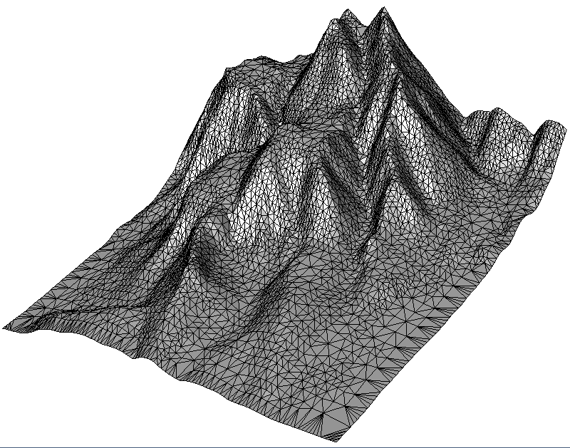
- Sub-Example 2 shows uniform simplification by a grid, where the user specifies the cell size. The algorithm summarizes all points within a grid cell.
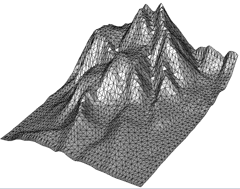
- Sub-Example 3 reduces the point cloud also with a grid, but determines the grid size itself to match the desired number of output points specified by the user.
// 1: Simplify: Adaptive, cluster points based on their height difference
void terrain_adaptiveSimplify()
{
  	...
 	// * 3 *   Reduce the cloud size
	double maxDiffZ(1.0); // z-tolerance per point group
	SumStrategy sms(SMS_AVERAGE); // or SMS_MEDIAN, SMS_MINIMUM, SMS_MAXIMUM
	ConvexHullStrategy chs(CHS_MAXHULL); // or CHS_NONE, CHS_MINHULL
	cloudPrep.adaptiveSimplify(maxDiffZ,sms,chs,false); // bDryRun=false
	...
}
// 2: Simplify: Use a grid to cluster points
void terrain_gridSimplify()
{
...
// * 3 * Reduce the cloud size
SumStrategy sms(SMS_AVERAGE); // or SMS_MEDIAN, SMS_MINIMUM, SMS_MAXIMUM
ConvexHullStrategy chs(CHS_MAXHULL); // or CHS_NONE, CHS_MINHULL
double gridLength(2);
cloudPrep.uniformSimplifyGrid(gridLength,sms,chs,false); // bDryRun=false
...
}// 3: Simplify: Use approxNumPoints to cluster points (also grid-based)
void terrain_numPointsSimplify()
{
...
// * 3 * Reduce the cloud size
SumStrategy sms(SMS_AVERAGE); // or SMS_MEDIAN, SMS_MINIMUM, SMS_MAXIMUM
ConvexHullStrategy chs(CHS_MAXHULL); // or CHS_NONE, CHS_MINHULL
double approxNumPoints(vInputPoints.size()/4);
cloudPrep.uniformSimplifyNum(approxNumPoints,sms,chs);
...
}
Two parameters in the above code need an explanation:
- The
SumStrategydetermines how points in a group are summarized. Most of the timeSMS_AVERAGEwill give good results. If the data contains outliers,SMS_MEDIANis more stable. Simple ground filtering can be achieved withSMS_MINIMUM, since selecting the lowest point in the cluster ignores those higher points corresponding to vegetation.SMS_MAXIMUMis also available. - The
ConvexHullStrategydetermines whether and which points of the convex hull must be left unchanged. The valueCHS_NONEignores the convex hull and simply treats all points the same.CHS_MAXHULLprotects all points of the convex hull i.e., it keeps them constant,CHS_MINHULLprotects only those points of the convex hull whose absence would change the shape of the convex hull. That is, it does not protect points that lie in the middle of a convex-hull line segment. - The commands return the resulting size of the point cloud. To determine the size in advance without actually simplifying the point cloud, the parameter
bDryRuncan be set to true.
Exporting the final Triangulation
You probably want to have your 2.5D Delaunay triangulation not only in the Fade library, but also bring it back into your own software. This must be quick, convenient and without the triangle mesh residing in memory twice at any point. There is now a ready-made solution for triangulation-export in Fade and the earlier Example 8 describes it already for the 2D case. But for self-containedness we treat this export-solution also with the present 2.5D terrain example: We use a simple struct to store all triangulation data:
“Note: Alternatively you can also save a Delaunay triangulation to a file and reload it later”
struct FadeExport
{
 void print() const;
 bool writeObj(const char* filename) const;
 void extractTriangleNeighborships(std::vector<std::pair<int,int> >& vNeigs) const;
 void getCornerIndices(int triIdx,int& vtxIdx0,int& vtxIdx1,int& vtxIdx2) const;
 void getCoordinates(int vtxIdx,double& x,double& y) const;

 // DATA
 double* aCoords; ///< Cartesian coordinates (dim*numPoints)
 int* aCustomIndices; ///< Custom indices of the points (only when exported)
 int* aTriangles; ///< 3 counterclockwise oriented vertex-indices per triangle (3*numTriangles)
};
// 4: Export data of the triangulation
void exportData()
{
	...
	Fade_2D dt;
	dt.insert(&cloudPrep,true);

	// * 3 *   Export to a struct
	FadeExport fadeExport; // Simple struct, see "FadeExport.h"
	bool bCustomIndices(true); // To retrieve custom indices also
	bool bClear(true); // Clear memory in dt to save memory
	dt.exportTriangulation(fadeExport,bCustomIndices,bClear);

	// All triangulation data is in 'fadeExport' now and dt has
	// been cleared during the export procedure to avoid memory
	// usage peaks: dt is empty now.

	// * 4 *   Show that all data is in fadeExport
	fadeExport.print();
	fadeExport.writeObj("exportTest25D.obj");

	// NOTE: You have full access to the data in the FadeExport struct
	// and you have also access to the source code because it has been
	// implemented only in the header file "FadeExport.h". Adapt it
	// to your needs. Have also a look at the similar example in the
	// examples_2D folder.
}
10 replies on “2.5D Terrain Triangulation and Point Cloud Simplification”
Hello,
I am a R&D Engineer at Penn State interested in extracting iso-contours from triangulated meshes.
We use CGAL in our research and would like to know more about terrain modeling and finding iso-contours from your experience.
Would you be able to discuss the process for terrain/bathymetric analysis or to help guide our approach?
We take in DEM data in an .xyz file, attain a 3D delaunay triangulation, “convert” the triangulation into a mesh, and use CGAL’s mesh-slicing functions. However this seems dreadfully slow. We are working on the scale of number of triangles (~500K) seen in your example, and would like to extract perhaps up to 100 contour levels at differing heights.
Would you be able to lend your experience/insight?
Thank you,
Robert
Hi,
I am not sure whether I have correctly understood your approach: Do you really put 3D points into a 3D Delaunay triangulation? The output is a convex tetrahedral complex and even if you use a fake point at infinity to extract an approximate surface representation, that will be very slow for two reasons: First, a tetrahedral mesh has more elements than a triangular mesh. Second, the math is more complex, especially due to the high number of almost degenerate tetrahedra that DEM data probably causes.
Fade2.5D should compute the ISO lines within a second. If your project is non-commercial I can give you a free research license, just send me an email with the details (research group, project leader, a short description of link to the project website)
Best regards
Bernhard
Hello,
I am a phd student of Wuhan University in point cloud processing.
Is there a function that can get all Vertices indice linked with a chosen point?
Hello,
you are right, such a function would probably be convenient. I can implement that for the next version. Meantime, let me provide this little piece of source:
[code]
void incidentIndices()
{
// * 1 * Create random points
vector<Point2> vInputPoints;
generateRandomPoints(25,0,10,vInputPoints,1);
// * 2 * Set indices
for(size_t i=0;i<vInputPoints.size();++i)
{
vInputPoints[i].setCustomIndex(i);
}
// * 3 * Insert the points, retrieve the vertex handles
Fade_2D dt;
vector<Point2*> vHandles;
dt.insert(vInputPoints,vHandles);
// * 4 * For a certain point handle, retrieve the incident triangles
Point2* pVtx(vHandles[0]);
vector<Triangle2*> vIncidentT;
dt.getIncidentTriangles(pVtx,vIncidentT);
// * 5 * Iterate over the triangles to fetch the indicent points
set<Point2*> vIncidentVtx;
for(vector<Triangle2*>::iterator it(vIncidentT.begin());it!=vIncidentT.end();++it)
{
Triangle2* pT(*it);
for(int i=0;i<3;++i)
{
Point2* pCorner(pT->getCorner(i));
if(pCorner!=pVtx) vIncidentVtx.insert(pCorner);
}
}
// * 6 * Print the indices
cout<<"Vertices incident to "<<pVtx->getCustomIndex()<<": ";
for(set<Point2*>::iterator it(vIncidentVtx.begin());it!=vIncidentVtx.end();++it)
{
Point2* pIncidentVtx(*it);
cout<<pIncidentVtx->getCustomIndex()<<" ";
}
// * 7 * Draw it
Visualizer2 v("triangles.ps");
dt.show(&v);
v.addObject(Label(*pVtx,std::to_string(pVtx->getCustomIndex()),true,25),Color(CRED));
for(set<Point2*>::iterator it(vIncidentVtx.begin());it!=vIncidentVtx.end();++it)
{
Point2* pIncidentVtx(*it);
v.addObject(Label(*pIncidentVtx,std::to_string(pIncidentVtx->getCustomIndex()),true,25),Color(CGREEN));
}
v.writeFile();
}
[/code]
Hi, I am working as a R&D engineer in a company. We are working on Fade2.5D. As a requirement, we need to visualize the 3D object on a viewer real-time. Is there any process? Please help me.
Hi!
Fade2.5D writes *.obj Files that can be viewed with virtually any 3D Viewer. But when you want to observe a triangulation in a GUI widget, you must program it or consult the documentation of your GUI toolkit vendor.
Thank you for your reply,
My system generates point cloud data real-time in each iteration. I did that and we got the .obj file and I can see it using windows 3D viewer. But In my work, I want to make or incorporate an in-built 3d viewer in my application to visualize that data as 3Dview
Thank you for your feedback. You can use Fade_2D::exportTriangulation() to retrieve all triangulation data in a convenient format. Then get the data into something from your GUI toolkit to visualize it. Maybe it makes also sense to have a look at the VTK project for that purpose. But I’m not a GUI expert.
Hallo,
I have already tried the FADE 2.5D on an x86 computer and I found the performance of Fade 2.5D is very good and the meshing speed is also fast.
I would like to continue using Fade 2.5D in my bachlor’s project at the university, but now I’ve switched to M1 Mac. I have tried to link your library for armV6/armV7 in a arm64 docker container on M1 Mac, but I got a compilation error. Yes, your x86 libraries can be compiled in a x86 docker container on M1 Mac, but I got always other Problems like Rviz, Gazebo when I use the x86 docker container on my Mac.
If possible, could you please generate a library for the M1 Architecture ( arm64 or/and armV8 )?
Hi Andy,
Yes, your suggestion makes sense and I will try to support M1 with the next release. Give me some time for that.