Polygon Clipping, Boolean Set Operations
Fade provides polygon clipping and functions to combine shapes through the boolean operations:
- Union (A OR B)
- Intersection (A AND B)
- Difference (A NOT B)
- Symmetric Difference (A XOR B)
You can find the C++ source code for the polygon clipping demo in examples_2D/ex5_booleanOps.cpp in the Fade download.
Creating two Shapes
“This demo code creates two input shapes using code similar to what was shown in Polygons and Zones – Example4. However, for the sake of completeness, we’ll provide a brief recap here:
	// * Step 1 *   Insert 4 bounding box points
	Fade_2D dt;
	dt.insert(Point2(0,0));
	dt.insert(Point2(+100,0));
	dt.insert(Point2(100,50));
	dt.insert(Point2(0,50));

	// * Step 2 *   Create points on two circles
	std::vector<Point2> vCircle0;
	std::vector<Point2> vCircle1;
	int numPoints(8);
	double radius(22);
	//generateCircle( num,centerX,centerY,radiusX,radiusY,vOut);
	generateCircle(numPoints,45.0,25.0,radius,radius,vCircle0);
	generateCircle(numPoints,55.0,25.0,radius,radius,vCircle1);

	// * Step 3 *   Create segments
	std::vector<Segment2> vSegments0;
	std::vector<Segment2> vSegments1;
	for(int i=0;i<numPoints;++i)
	{
		Segment2 seg0(vCircle0[i],vCircle0[(i+1)%numPoints]);
		Segment2 seg1(vCircle1[i],vCircle1[(i+1)%numPoints]);
		vSegments0.push_back(seg0);
		vSegments1.push_back(seg1);
	}

	// * Step 4 *   Insert the segments as constraint graphs.
	ConstraintGraph2* pCG0=dt.createConstraint(vSegments0,CIS_CONSTRAINED_DELAUNAY);
	ConstraintGraph2* pCG1=dt.createConstraint(vSegments1,CIS_CONSTRAINED_DELAUNAY);

	// * Step 5 *   Create two Zone2 objects using ZL_INSIDE:
	//         Note: Boolean operations require that the two zones
	//         belong to the same Fade_2D object!
	Zone2* pZone0(dt.createZone(pCG0,ZL_INSIDE));
	pZone0->show("example5_zone0.ps",true,true);

	Zone2* pZone1(dt.createZone(pCG1,ZL_INSIDE));
	pZone1->show("example5_zone1.ps",true,true);
- Step 1: Create a Fade_2D object and insert four bounding box points.
- Step 2: Generate circle points, storing them in the vectors
vCircle0andvCircle1. - Step 3: Create line segments, store them in
vSegment0andvSegment1. - Step 4: Create the two ConstraintGraph2 objects,
pCG0andpCG1, using the segments fromStep 3as input. - Step 5: Create two
Zone2objects insidepCG0andpCG1, and then draw them.
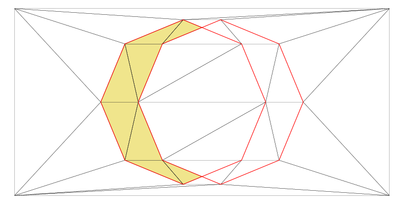
pCG0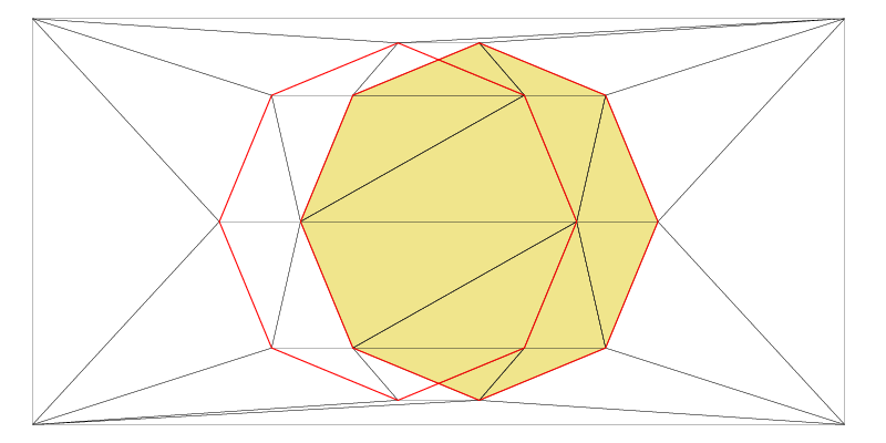
pCG1In the above image, please note that pCG0 and pCG1 intersect each other. As a result, Fade automatically subdivides the intersecting constraint segments.
“Fade computes challenging segment intersections with multiple-precision arithmetic, and therefore, the result is numerically robust against glancing intersections. However, it’s important to be aware that the final result is represented in double-precision numbers, which means there’s a possibility of rounding.“
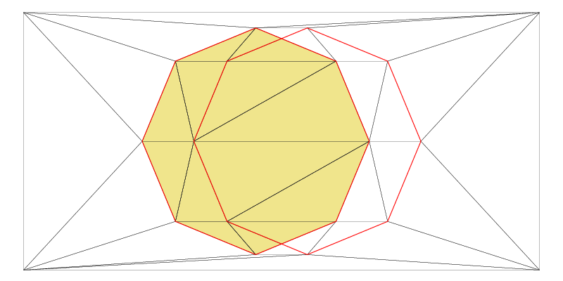
Boolean operations with polygons (zones)
Previously, we have made two Zones (Shapes) in the same Fade_2D instance. Now, the following C++ example demonstrates how to combine these shapes with just one more line of code. Four different boolean shape operations are available for this purpose. The resulting images are displayed below:
// Union operation
Zone2* pZoneUnion(zoneUnion(pZone0,pZone1));
pZoneUnion->show("example5_zoneUnion.ps",true,true);
// Intersection operation
Zone2* pZoneIntersection(zoneIntersection(pZone0,pZone1));
pZoneIntersection->show("example5_zoneIntersection.ps",true,true);
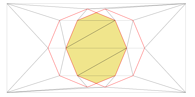
// Difference operation
Zone2* pZoneDifference(zoneDifference(pZone0,pZone1));
pZoneDifference->show("example5_zoneDifference.ps",true,true);
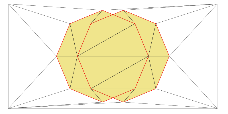
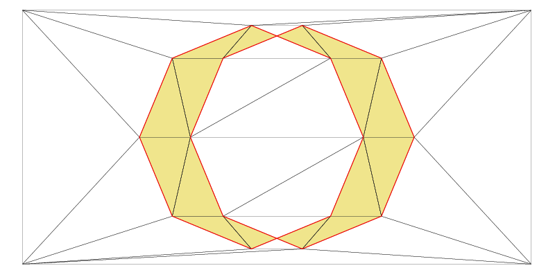
// Symmetric Difference operation
Zone2* pZoneSymmetricDifference(zoneSymmetricDifference(pZone0,pZone1));
pZoneSymmetricDifference->show("example5_zoneSymmetricDifference.ps",
true,true);
Extracting triangles and Border Polygons
You can use Zone2::getTriangles() to conveniently extract the triangles of a zone. However, if you are rather interested in its boundary, use Zone2::getBorderEdges() to retrieve a vector of Edge2 objects.
“You may find it helpful to know that an
Edge2object consists of aTriangle2and anintra-triangle-indexthat identifies the edge. An edge has a specific direction, which is always counterclockwise around its triangle.”
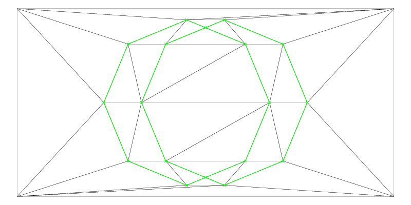
The Zone2::getBorderEdges() command returns edges of one or more contours in arbitrary order. Sometimes, you’ll want to convert such an edge-soup into one or more polygons. You can achieve this using the edgesToPolygons() function, as shown below:”:
// * 7 *   Retrieve the (oriented but unordered) border edges of
//         pZoneSymmetricDifference
vector<Edge2> vBorders;
pZoneSymmetricDifference->getBorderEdges(vBorders);
Visualizer2 v("example5_symDiffBorders.ps");
dt.show(&v,false); // show only the triangles
v.addObject(vBorders,Color(CGREEN,0.5,true));
v.writeFile();

// * 8 *   Turn the border edges into polygons
vector<Edge2> vRemainingEdges;
vector<vector<Edge2> > vvEdges;
edgesToPolygons(vBorders,vvEdges,vRemainingEdges);

// * 9 *   Draw
Visualizer2 polyVis("example5_polygons.ps");
pZoneSymmetricDifference->show(&polyVis,false,false); // show only the triangles
for(size_t poly=0;poly<vvEdges.size();++poly)
{
	const vector<Edge2>& vPolygon(vvEdges[poly]);
	Color c(Color::getNextColorName(),1.0,false); // Next color from a (repeating) sequence
	for(size_t j=0;j<vPolygon.size();++j)
	{
		const Edge2& edge(vPolygon[j]);
		polyVis.addObject(edge,c);

		Point2* pSourcePoint(edge.getSrc());
		Label lab(*pSourcePoint,toString(j),true,16);
		polyVis.addObject(lab,c);
	}
}
polyVis.writeFile();
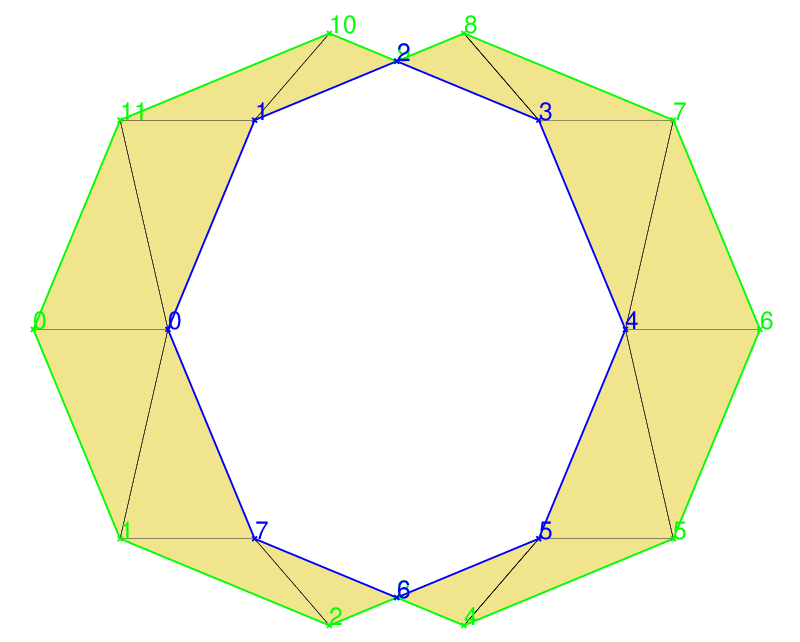
“As mentioned earlier,
Edge2objects are oriented counterclockwise with respect to their triangle. It’s important to note that this results in the outer polygon in this example being oriented counterclockwise, while the inner one is oriented clockwise. This property can be useful in various scenarios!“
This post has demonstrated how to combine polygonal areas using set operations and how to extract the boundary polygons of the resulting area. The more challenging situation where the inputs are polygons with holes will be covered in our next article. However, it’s worth noting that Zone2 objects can also be defined for the purpose of creating high-quality triangular meshes inside them, as discussed in our article Example7 – Mesh Generation.
6 replies on “Polygon Clipping, Boolean Operations – Example5”
Good day. My name is Boris, I am a student from Moscow Institute of Physics and Technology. It would be really cool if you could help me with the following situation:
In your example above you define coordinates of points of one polygon like coordinates of points of another polygon plus 90 and as a result, we have two intersecting polygons where all intersecting segments intersect only at one point. And everything is going fine. But if I change 90 to 60 everything is change and two leftmost segments start to intersect in infinite amount of points. Triangulation is still going fine but problem occurs when I try to call getBorderEdges() method of an pZoneUnion object. It writes values to std::vector in a wrong order and resulting figure doesn’t have any similarity with one I am waiting for. So the question is: Did I miss some functionality to solve this situation? And if I didn’t is there some way to solve it?
Dear Boris,
The documentation of getBorderEdges() says that the edges are CCW oriented, i.e. they point in counterclockwise direction but they are NOT necessarily ordered. I admit, this is misleading. Next week a new version will be released and then this issue will be solved. However, visualization works when you add this code to example5.cpp:
It shows the the correct border of the union of the two shapes. If you need the segments in the right order, please use the sortRing function from freeFunctions.h.
hth
Dear Bernhard,
thank you! Your answer helped me very much. Now I have another problem and I try to find a way of solving it. I want to find a union of two nonconvex polygons and it’s possible that some number of holes will appear inside this union. Awesome getBoundarySegments() method in combination with sortRing() method properly return outer circuit. But is there some way to find circuits of holes inside this union?
Thank you,
Boris
Dear Boris,
Yes. A new release was due anyway and I have added that feature. Please download Fade2D v1.58. Extract the edges of the union zone using Zone2::getBoundaryEdges() and then use the edgesToPolygons() function to organize these edges as polygons. I have added demo code to example5.cpp, see also the description above (added right now) and the Documentation of edgesToPolygons
Hi,
My name is Bastien and I am currently working on a 3D engine. I’m interested in adding Boolean operations in it. I tried to do a simple case by reusing your example5, but I’m told that my shape is not a closed polygon. I really don’t understand why because it’s a simple square. Am I doing something wrong ?
Here is my code :
Fade_2D dt;
// * 2 * Prepare two vectors of Segments
std::vector vSegments1;
// square
Point2 p0(0,0);
Point2 p1(2,0);
Point2 p2(2,2);
Point2 p3(0,2);
vSegments1.push_back(Segment2(p0,p1));
vSegments1.push_back(Segment2(p1,p2));
vSegments1.push_back(Segment2(p2,p3));
vSegments1.push_back(Segment2(p3,p1));
// inner hole
std::vector vSegments2;
Point2 h0(0.5,0.5);
Point2 h1(1.5,0.5);
Point2 h2(1.5,1.5);
Point2 h3(0.5,1.5);
vSegments2.push_back(Segment2(h0,h1));
vSegments2.push_back(Segment2(h1,h2));
vSegments2.push_back(Segment2(h2,h3));
vSegments2.push_back(Segment2(h3,h1));
// * 3 * Use the segments to create two ConstraintGraphs. Then show what we have
ConstraintGraph2* pCG1=dt.createConstraint(vSegments1,CIS_CONSTRAINED_DELAUNAY);
ConstraintGraph2* pCG2=dt.createConstraint(vSegments2,CIS_CONSTRAINED_DELAUNAY);
dt.show(“example5_constraints.ps”);
// Make sure pCG1 and pCG2 are closed
if(!pCG1->isPolygon() || !pCG2->isPolygon() )
{
std::cout<<"pCG1 and pCG2 must be closed polygons, stop"<show(“example5_zone0.ps”,true,true); // all triangles=true, show constraints=true
Hi Bastien,
this is not a polygon:
vSegments1.push_back(Segment2(p0,p1));
vSegments1.push_back(Segment2(p1,p2));
vSegments1.push_back(Segment2(p2,p3));
vSegments1.push_back(Segment2(p3,p1));
The last line should contain a segment from p3 to p0.
Best regards
Bernhard