If you want to triangulate a polygon or define a polygonal area in a triangulation, you’re in the right place. A Zone2 represents a region within a triangulation, and it can be defined directly or as the result of combining other zones through Boolean operations. Here’s a list of possible Zone2 types categorized by their ZoneLocation:
ZL_GLOBAL: The entire triangulation.ZL_INSIDE: The area inside a polygon.ZL_OUTSIDE: The region outside a polygon.ZL_GROW: A region grown from a seed point up to defined boundaries OR a region defined by a specific set of triangles.ZL_RESULT: The result of Boolean operations; you can combine zones through union, difference, symmetric difference, and intersection as described in the next article Boolean Set Operations.
For a practical demonstration of Zone2s, refer to the code snippets below.
Preparing a Triangulation and the Polygons
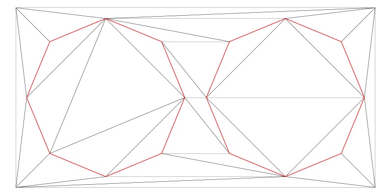
Example 4 consists of two major parts: The first one prepares a triangulation and two ConstraintGraph2 objects, as shown in the below image, and the second one will use them to create various Zone2 objects. Let’s focus on the first part now:
// Step 1: Create a Delaunay triangulation dt,
// and insert 4 points
Fade_2D dt;
dt.insert(Point2(0,0));
dt.insert(Point2(+100,0));
dt.insert(Point2(100,50));
dt.insert(Point2(0,50));

// Step 2: Create circles, repair and orient them, if
// required, and create *oriented* ConstraintGraph2 objects
vector<Segment2> vSegments0,vSegments1;
createCircles(vSegments0,vSegments1);
ConstraintGraph2* pCG0=createOrientedConstraint(dt,vSegments0);
ConstraintGraph2* pCG1=createOrientedConstraint(dt,vSegments1);

// Step 3: Visualize the triangulation, the constraint
// segments, and also the vertex indices, if any.
Visualizer2 v("example4_constraints.pdf");
dt.show(&v,true); // true means: highlight the constraints
vector<Point2*> vVertices;
dt.getVertexPointers(vVertices);
for(Point2* pVtx:vVertices)
{
	if(pVtx->getCustomIndex()>-1) // -1 is just the default index
	{
		Label l(*pVtx,to_string(pVtx->getCustomIndex()).c_str());
		v.addObject(l,Color(CBLACK));
	}
}
v.writeFile();
In Step 1 of this code we create a Delaunay triangulation dt and insert four points. In Step 2 we store two circles to vSegments0 and vSegments1, and create two ConstraintGraph2 objects using the helper function createOrientedConstraint(), which we will discuss in the next section. Finally, Step 3 visualizes the result, as shown in the image below.
Creating Oriented ConstraintGraph2 Objects
When we create a ConstraintGraph2 for later Zone2 creation, we must ensure three properties:
- The polygon’s segments must be free of self-intersections.
- The segments must be oriented counterclockwise (CCW) around the polygon’s area.
- We must assure the
ConstraintGraph2that the segments are oriented.
In the createOrientedConstraint() function below, we ensure the Conditions 1 and 2 using the PolygonClipper, which repairs and reorients the polygon segments. The third requirement is satisfied by calling createConstraint() with 'true' as the third argument, corresponding to the parameter bool bOrientedSegments.
The code snippet below shows the implementation of the createOrientedConstraint() helper function used in the previous section.
ConstraintGraph2* createOrientedConstraint(Fade_2D& dt,vector<Segment2>& vPolygon)
{
  // * 1 *   Check the input
  if(vPolygon.empty())
  {
      std::cout<<"createOrientedConstraint(): No segments"<<std::endl;
      return NULL;
  }

  // * 2 *   Repair self-intersections, if any, and orient the edges
  //         counterclockwise around the polygon's area
  PolygonClipper clip(vPolygon,0);
  vector<Segment2> vProperPolygon;
  clip.getSegments_regionOriented(vProperPolygon);
  if(vProperPolygon.empty())
  {
      std::cout<<"createOrientedConstraint(): Repaired polygon is empty"<<std::endl;
      return NULL;
  }

  // * 3 *   Create an *oriented* ConstraintGraph2
  ConstraintGraph2* pCG;
  pCG=dt.createConstraint(vProperPolygon,CIS_CONSTRAINED_DELAUNAY,true); // 'true' guarantees CCW orientation
  return pCG;
}
If you’re familiar with an earlier version of this article and code, you might notice that previous versions didn’t require explicit orientation of polygon segments, as done in the above function. That’s still an option: you can create
ConstraintGraph2objects exactly as before, without orienting the segments and without settingbOrientedSegments=truewhen callingcreateConstraint(). In this case, the createdConstraintGraph2object will attempt to orient the segments automatically; though this method has always been limited to simple polygons without holes. In contrast, the new approach removes this limitation and is safer, as it automatically resolves polygon issues.
Creating Various Types Of Zones
Now that we have two reliable ConstraintGraph2 objects, we can start to test the various ways to create Zone2 objects.
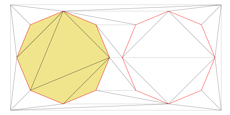
Zones Inside and Outside of Polygons
The ConstraintGraph2 object pCG1 represents the left circular polygon in the image above. Now, let’s proceed to create a Zone2 inside this polygon and another one outside of it using ZL_INSIDE respectively ZL_OUTSIDE as ZoneLocation value.
// Step 4: Zones inside and outside pCG0:
Zone2* pZoneInside(dt.createZone(pCG0,ZL_INSIDE));
pZoneInside->show("example4_zoneInside.pdf",true,true); // all triangles=true, highlight constraints=true
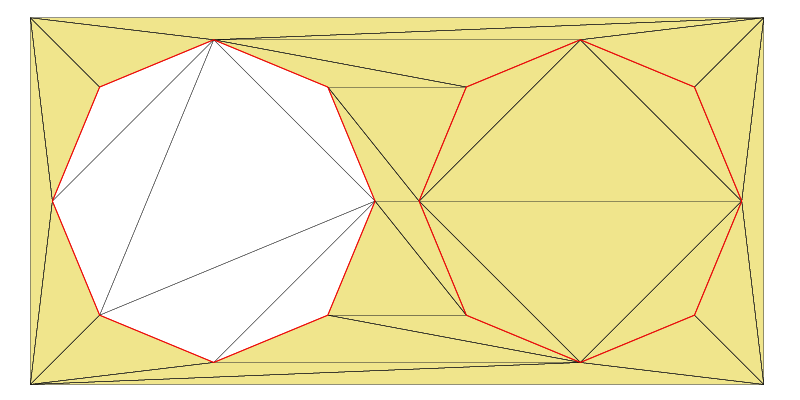
Zone2* pZoneOutside(dt.createZone(pCG0,ZL_OUTSIDE));
pZoneOutside->show("example4_zoneOutside.pdf",true,true);
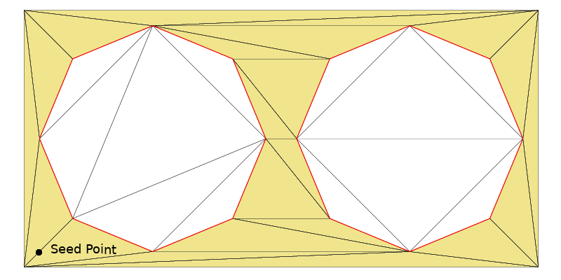
Zones Grown from a Seed Point
Zones can also be defined as the area that grows from a seed point, stopping when it reaches specified ConstraintGraph2 objects that act as boundaries, or “fences”.
vector<ConstraintGraph2*> vCG;
vCG.push_back(pCG0);
vCG.push_back(pCG1);
Point2 seedPoint(5.0,5.0); // Point near the lower left corner
Zone2* pZoneGrow(dt.createZone(vCG,ZL_GROW,seedPoint));
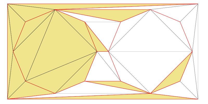
pZoneGrow->show("example4_zoneGrow.ps",true,true);
The provided code creates a vector that holds the previously created ConstraintGraph2 objects pCG0 and pCG1. It then sets a seed point near the lower-left corner of the image and grows a Zone2 from this seed point. The growing process stops at pCG0 and pCG1, effectively enclosing the zone within these boundaries.
The Global Zone
A global zone consists of all existing triangles. It is created using the ZoneLocation ZL_GLOBAL.
Zone2* pZoneGlobal(dt.createZone(NULL,ZL_GLOBAL));
pZoneGlobal->show("example4_zoneGlobal.ps",true,true);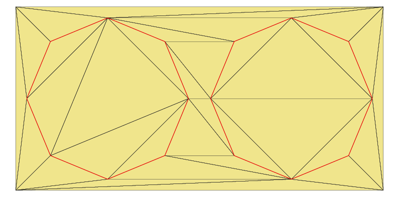
Zone Creation from Arbitrary Triangles
You can also create a Zone2 from arbitrary triangles, whether connected or not. To illustrate this, the code below initially retrieves all triangles from the triangulation. It then selects only half of them to create a Zone2.
// + Zone defined by specific triangles
vector<Triangle2*> vT;
dt.getTrianglePointers(vT);
vT.resize(vT.size()/2);
Zone2* pZoneFromTriangles(dt.createZone(vT));
pZoneFromTriangles->show("example4_zoneFromTriangles.ps",true,true);
This article covered the creation of zones, using the PolygonClipper to correct potentially corrupted input polygons, while the next post Zone Operations demonstrates the computation of the union, the intersection, the difference and symmetric difference of such zones.
